Home-made keyboard
We wanted to learn how to get the Pi to take inputs from push buttons. Making a keyboard seemed like a good idea. An extra ambition we had was that we wanted the sound played by the keyboard to be made by ourselves. This required us to learn how to do sound recording and editing in Python. It also posted some additional programming challenges, such as what to do when multiple keys (buttons) were pressed simultaneously.
Setting up the python environment
Before we can use pip to install the necessary supporting python packages, we need first install the system libraries that these packages are built on.
The soundfile module depends on the system library libsndfile, which can be installed by
sudo apt-get install libsndfile1
The sounddevice module depends on numpy. Unfortunately, on my Pi, simply installing using pip install numpy did not work; when importing the module, I got an error message that contained the phrase
ImportError: libopenblas.so.0: cannot open shared object file: No such file or directory
This can be solved by using
sudo apt-get install libopenblas-dev
Visit the following website for other solution to numpy import errors:
https://numpy.org/devdocs/user/troubleshooting-importerror.html
Once the system libraries are installed, use the following commands to create a virtual environment.
git checkout db33bddf05edd9c1b003cf5c14b51fd0fef5cdff
python -m venv --copies --clear ./venv
source venv/bin/activate
pip install -r requirements.txt
export PYTHONPATH=path_to_src_folder  # This is the src folder inside the repo
Sound recoding and editing
We are luckily enough to have a little musician in the household who knows how to play the flute. We did not want to make a very large keyboard, but just one that had enough keys to let us play a classic song :-)

So the following were what we ended up doing:
- Wrote a little program to record sounds (
src/home_made_keyboard/recording.py). - Went to the quietest room in the house, and Jim played the six notes needed for the song. Each note was saved in a separate
flacfile. - Inspected wave forms of the recordings to find out where the useful bits were. We double checked, using
src/home_made_keyboard/audio_editor.py, that the sections suggested by the wave forms did sound good, and that repeated it did not sound too odd (we had to accept that these homemade recordings were not going to be perfect). - Used
src/home_made_keyboard/audio_trimmer.pyto trim the original recordings and only kept the sections that we needed.
Electronics basics
When looking into writing code to respond to push button signals, two unfamiliar terms kept popping up: pull-up and pull-down. So we spent sometime trying to understand the basics, just so that we wouldn't blow up the Pi :-).
A TL;DR summary of what we found is:
- Use the built-in pull-up resistor if one side of the button is connected to ground, and the other to a GPIO pin.
- Use the built-in pull-down resistor if one side of the button is connected to a 3V3 pin, and the other to any GPIO pin.
The state of a digital logic gate (pin)
When a GPIO pin is connected to a push button, we are effectively using the pin as a digital logic gate. A logic gate has two state: high and low. If the voltage from the pin of the chip to the chip's ground is below , then the pin's state is regarded as low. If the input voltage is above , then its state is regarded as high. Obviously, . The interval is known as the indeterminate region, in which the state of the pin is neither high nor low. The purpose of pull-up/pull-down resisitors are to tie the state of the pin to high/low, by, e.g., preventing accidental switching of state due to interference. They also control the current flow and prevent short circuit.
Pull-up resistors
If we want high as the default state of the pin and want to change the state to low by pushing the button, we use pull-up resistors, as shown below. When the switch is open (off), there is a high voltage from B to C, leaving the pin in the high state. When the switch is closed (on), the current, after passing the pull-up resistor, flows directly to ground (D), because the impedance of the chip is typically very high. Thus, the pin is connected to ground (0V) and assumes the low state.
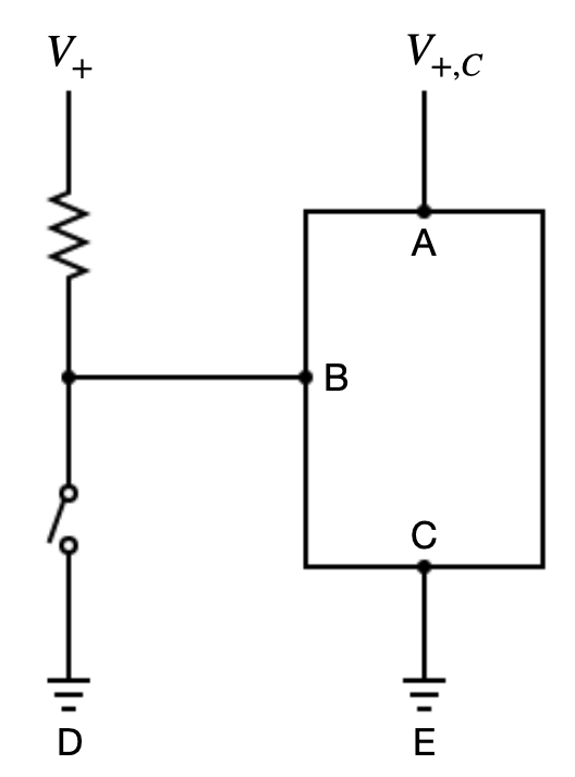
Note that if the pull-up resistor is removed, when the switch is closed, there is a direct short circuit between and ground, which creates excessive current flow and may damage the circuit.
Note that the job of the chip is to measure the voltage from the input pin B to the chip's ground C. When the swich is open, the current flows from to B and to C. There is resistance between B and C, denoted by . The minimum input current for pin B that is required for the chip to work is denoted by . The voltage drops as the current flows through the pull-up resistor. We need to make sure that the remaining voltage is at least so that the pin is in the high state. Thus, the maximum allowable resistance is
where is the maximum sink current (the ability of the port to receive current). Normally resistors with lower resistance are used because we want to guarantee that the state of the pin is high after the input current passing through the pull-up resistor.
Pull-down resistors
Recall that the chip's job is to measure the voltage from the input pin B to its ground C. When the switch is open, B is effectively connected to ground. So there is a low voltage from B to C. When the swtich is closed, then B has voltage and the pin is in the high state.
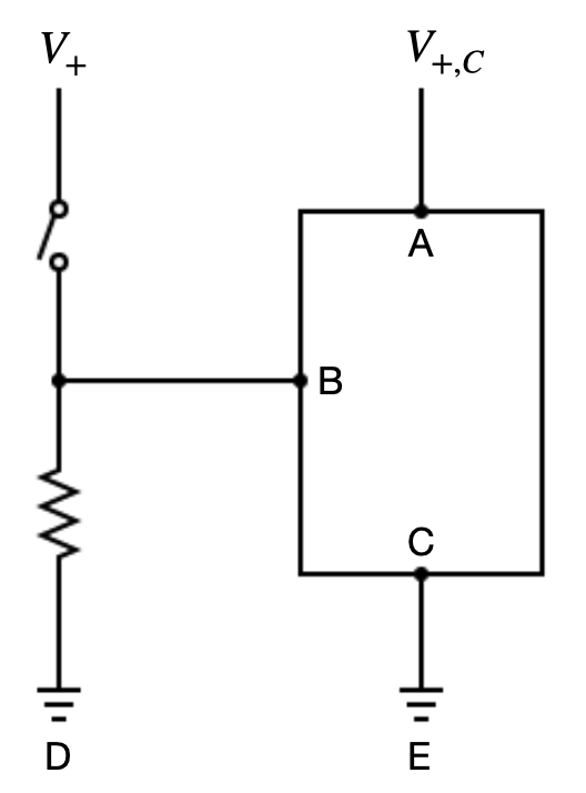
Note that if we remove the section that includes D (ground) and the pull-down resistor, then when the switch is open, the input pin becomes analogous to an antenna, liable to picking up electrical signals generated by external sources or the chip itself. The pin is in a floating state, and could fluctuate between high and low.
To calculate the maximum allowable resistance value for the pull-down resistor, note that, when the switch is open, current flows from to A to B and finally to D. As the current flows from A to B, there will be a voltage drop due to resistance, denoted by . Let the maximum current sourcing ability (i.e., the maximum current flowing out of the pin) be . Because we have two resistors in series, and because D is ground with voltage 0, the total voltage drop is . We need to ensure that after the drop caused by , the remaining voltage is lower than , to ensure that when the switch is open, the input pin is in the low state. Thus, the maximum resistance value of the pull-down resistor must satisfy
Wiring up the buttons and programming
We used the built-in pull-up resistors. So the wiring was straightforward, as shown below by Jim
The GPIO pins and the paths of the edited recodings were hard-coded in main() in src/home_made_keyboard/home_made_keyboard.py.
To allow chords to be played when multiple keys were pressed at the same time, we used a separate subprocess to monitor each button.
To run the program, use
export PYTHONPATH=path_to_src_folder  # This is the src folder inside the repo
python -m home_made_keyboard.home_made_keyboard